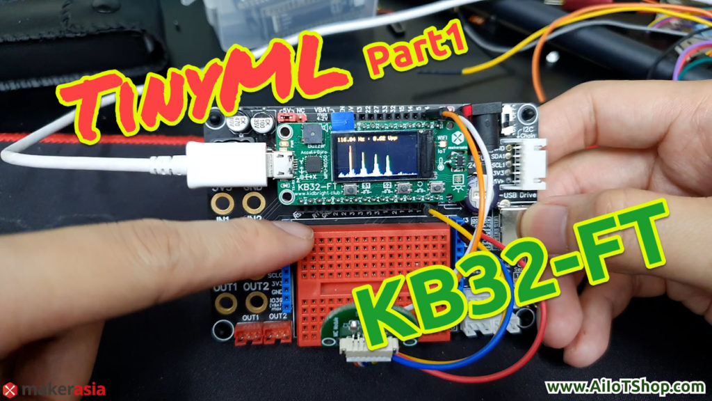
สวัสดีครับ วันนี้ผมจะมาสอนเพื่อนๆลองสร้างตัว Machine Learning บนบอร์ด KB32-FT กัน
โดยเราจะลองทำตัวอย่างการแบ่งแยกคำ (Word Classification) ที่จะทำการสอนให้บอร์ดรู้จักกับคำพูดต่างๆ เช่น หนึ่ง, สอง, สาม, เปิด และปิด ซึ่งเราจะทำการสอน AI แบบที่เรียกว่า Supervised learning
โดยบทความนี้จะถูกแบ่งออกเป็น 3 Part โดย
Part 1 จะเป็น Learning Phase : pre-processing, สร้าง datasets
Part 2 จะเป็น Learning Phase : Create Model, Train Model, Convert model
Part 3 จะเป็น Inference Phase
Part 1 Learning Phase : pre-processing, สร้าง datasets
VDO ประกอบ
งั้นเรามาเริ่มส่วนแรกเลยนะครับ ส่วน learning phase จะเป็นการสร้างเอไอเพื่อที่จะให้เรียนรู้สิ่งที่เราต้องการ ดังนั้นในส่วนนี้ก็จะมีการสร้างชุดข้อมูล (datasets), การเตรียมตัวชุดข้อมูลและAI, การสอน AI (Train) โดยการทำ Word Classification โดย Framework ที่ใช้สร้าง train และ แปลง จะใช้ TensorFlow ส่วน Framework ที่ใช้เขียนโปรแกรมบนบอร์ด KB32-FT จะใช้ Arduino-ESP32 นะครับ

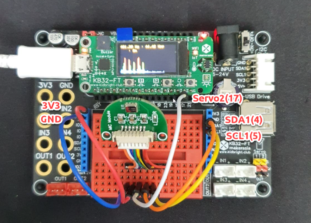
ผมจะใช้เซ็นเซอร์ ไมโครโฟนแบบดิจิตอล ที่มี เอาท์พุต เป็น I2S เบอร์ MSM261S4030H0 เพื่อให้เราได้เสียงที่มีคุณภาพ ซึ่งตัวบอร์ด KB32-FT ที่ใช้ชิป ESP32 นั้นมีโมดูลภายในที่สามารถอ่านเซ็นเซอร์แบบ I2S ได้อยู่แล้วทำให้เราสะดวกมากขึ้น (ไมค์ตัวนี้แบบเอาของบอร์ด CorgiDude มาใช้ใครสนใจซื้อได้จาก LINK )

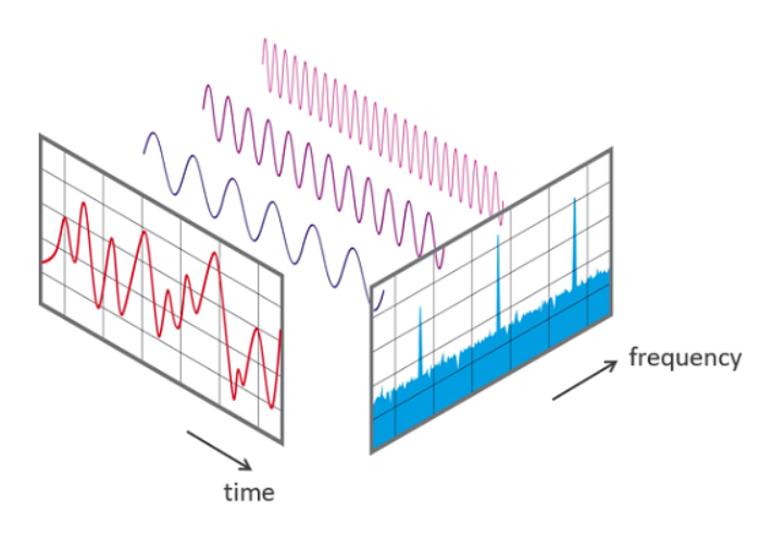
โดยในการที่จะทำให้ AI รู้จักคำพูดต่างๆ ที่เราพูดนั้น เพื่อให้เป็นการง่าย เราจะช่วยแยก Feature ของแต่ละคำที่เราพูดออกมา โดยใช้การแปลง Fourier transforms แยกองค์ประกอบของความถี่แต่ละเสียงที่เราพูดออกมา และส่ง Feature นี้เข้าไปยัง input ของ neural network (neural network คือโครงสร้างเซลล์สมองของ AI นั้นเอง ) เพื่อให้ AI สามารถเข้าใจรู้จักเสียงแต่ละเสียงได้ครับ
ดังนั้นก่อนอื่นเลยเราจะต้องทำการสร้าง datasets เพื่อที่จะสอน AI ให้รู้จักกับคำต่างๆ โดยผมจะสอนคำว่า หนึ่ง, สอง, สาม, เปิด และปิด โดยผมจะเก็บ datasets องค์ประกอบของเสียงตัวอย่างตัวอย่างละ 30 ถึง 40 ชุดคำ พร้อมบอกด้วยว่าเสียงนั้นคือเสียงอะไร(label) เพื่อใช้สอน(train) และทดสอบความแม่นยำ(validate)ของ AI ก่อนที่จะทำมาใช้จริง
การต่อสาย Jumper สามารถเสียบบนบอร์ดทดลองได้เลย สะดวกมากๆ
ก่อนอื่นเราไปดูตัวอย่าง code ที่ใช้สร้าง datasets กันเลย
โค้ดส่วนนี้จะเป็น การเรียก Library ที่ต้องการใช้งานเข้ามาใช้, การกำหนดค่า Parameter การทำงานต่างๆ รวมถึงลูปการเรียกอ่าน ค่าจาก Sensor Microphone ซื่งลูป นี้ผมจะให้ทำงานบน CPU ตัวที่ 2 แยกกับ CPU หลัก ให้สามารถงานได้อิสระ จาก code การทำงานหลัก
// #define debug // uncomment for debug

#define INTERVAL_Hz 2285.0f // 16000/7
#define FFT_N 128 // Must be a power of 2
#define TOTAL_TIME ((float)FFT_N/INTERVAL_Hz) //The time in which data was captured. This is equal to FFT_N/sampling_freq
#define SOUND_THRESHOLD 0.05f


#include <arduino.h>
#include "FFT.h" // include the library
#include <TFT_eSPI_KB32.h> // Hardware-specific library
#include "colormap.h" // include the library

#include <driver/i2s.h> // Hardware i2s module
#define bck_io_pin   17     //Servo2
#define ws_io_pin    4     //SDA1
#define data_in_pin  5     //SCL1


const i2s_port_t I2S_PORT = I2S_NUM_0;
volatile float adc_reading;


TFT_eSPI_KB32 tft = TFT_eSPI_KB32();

float fft_input[FFT_N];
float fft_output[FFT_N];

float max_magnitude = 0;
float fundamental_freq = 0;
float backgroundSound = 0;

uint32_t time_interval = 0;
volatile uint16_t fft_input_index = 0;
uint16_t x, y;
volatile uint8_t display_mode = 0;

char print_buf[300];

fft_config_t* real_fft_plan;

void i2sInit()
{
    Serial.println("Configuring I2S...");
    esp_err_t err;

    // The I2S config as per the example
    const i2s_config_t i2s_config = {
        .mode = i2s_mode_t(I2S_MODE_MASTER | I2S_MODE_RX), // Receive, not transfer
        .sample_rate = 16000,                         // 16KHz
        .bits_per_sample = I2S_BITS_PER_SAMPLE_32BIT, // could only get it to work with 32bits
        .channel_format = I2S_CHANNEL_FMT_ONLY_RIGHT, // although the SEL config should be left, it seems to transmit on right
        .communication_format = i2s_comm_format_t(I2S_COMM_FORMAT_I2S | I2S_COMM_FORMAT_I2S_MSB),
        .intr_alloc_flags = ESP_INTR_FLAG_LEVEL1,     // Interrupt level 1
        .dma_buf_count = 4,                           // number of buffers
        .dma_buf_len = 8                              // 8 samples per buffer (minimum)
    };

    // The pin config as per the setup
    const i2s_pin_config_t pin_config = {
        .bck_io_num = bck_io_pin,   // BCKL
        .ws_io_num = ws_io_pin,    // LRCL
        .data_out_num = -1, // not used (only for speakers)
        .data_in_num = data_in_pin   // Data
    };

    // Configuring the I2S driver and pins.
    // This function must be called before any I2S driver read/write operations.
    err = i2s_driver_install(I2S_PORT, &i2s_config, 0, NULL);
    if (err != ESP_OK) {
        Serial.printf("Failed installing driver: %d\n", err);
        while (true);
    }
    err = i2s_set_pin(I2S_PORT, &pin_config);
    if (err != ESP_OK) {
        Serial.printf("Failed setting pin: %d\n", err);
        while (true);
    }
    Serial.println("I2S driver installed.");
}

void reader(void* pvParameters) {
    uint8_t sampling_devider = 0;
    while (1)
    {
        int32_t sample = 0;
        int bytes_read = i2s_pop_sample(I2S_PORT, (char*)&sample, portMAX_DELAY); // no timeout
        if (bytes_read > 0) {
            sampling_devider++;
            adc_reading = (float)(sample >> 16) / 32767.0 * 10; // normalize to 10
            if (fft_input_index < FFT_N && sampling_devider == 7) {
                sampling_devider = 0;
                real_fft_plan->input[fft_input_index] = adc_reading;
                fft_input_index++;
            }
        }
    }
}

float  readMic() {
    return adc_reading;
}

void calibrate() {
    int i = 0;
    backgroundSound = 0;
    while (i < 200) {
        if (micros() - time_interval >= (1000000L / INTERVAL_Hz)) {
            time_interval = micros();
            backgroundSound += abs(readMic());
            i++;
        }
    }
    backgroundSound /= 200;

#ifdef debug
    Serial.print("Background sound level is ");
    Serial.println(backgroundSound);
#endif
}

void IRAM_ATTR S1_pressed() {
    display_mode = 0;
}

void IRAM_ATTR S2_pressed() {
    display_mode = 1;
}void i2sInit()
{
    Serial.println("Configuring I2S...");
    esp_err_t err;

    // The I2S config as per the example
    const i2s_config_t i2s_config = {
        .mode = i2s_mode_t(I2S_MODE_MASTER | I2S_MODE_RX), // Receive, not transfer
        .sample_rate = 16000,                         // 16KHz
        .bits_per_sample = I2S_BITS_PER_SAMPLE_32BIT, // could only get it to work with 32bits
        .channel_format = I2S_CHANNEL_FMT_ONLY_RIGHT, // although the SEL config should be left, it seems to transmit on right
        .communication_format = i2s_comm_format_t(I2S_COMM_FORMAT_I2S | I2S_COMM_FORMAT_I2S_MSB),
        .intr_alloc_flags = ESP_INTR_FLAG_LEVEL1,     // Interrupt level 1
        .dma_buf_count = 4,                           // number of buffers
        .dma_buf_len = 8                              // 8 samples per buffer (minimum)
    };

    // The pin config as per the setup
    const i2s_pin_config_t pin_config = {
        .bck_io_num = bck_io_pin,   // BCKL
        .ws_io_num = ws_io_pin,    // LRCL
        .data_out_num = -1, // not used (only for speakers)
        .data_in_num = data_in_pin   // Data
    };

    // Configuring the I2S driver and pins.
    // This function must be called before any I2S driver read/write operations.
    err = i2s_driver_install(I2S_PORT, &i2s_config, 0, NULL);
    if (err != ESP_OK) {
        Serial.printf("Failed installing driver: %d\n", err);
        while (true);
    }
    err = i2s_set_pin(I2S_PORT, &pin_config);
    if (err != ESP_OK) {
        Serial.printf("Failed setting pin: %d\n", err);
        while (true);
    }
    Serial.println("I2S driver installed.");
}

void reader(void* pvParameters) {
    uint8_t sampling_devider = 0;
    while (1)
    {
        int32_t sample = 0;
        int bytes_read = i2s_pop_sample(I2S_PORT, (char*)&sample, portMAX_DELAY); // no timeout
        if (bytes_read > 0) {
            sampling_devider++;
            adc_reading = (float)(sample >> 16) / 32767.0 * 10; // normalize to 10
            if (fft_input_index < FFT_N && sampling_devider == 7) {
                sampling_devider = 0;
                real_fft_plan->input[fft_input_index] = adc_reading;
                fft_input_index++;
            }
        }
    }
}
โค้ดส่วนนี้จะเป็นการ initainze โมดูลภายใน USART, I2S, GPIO, จอLCD, ปุ่มกด(ทำงานแบบ Interrupt), FFT ครับ
void setup() {

    Serial.begin(115200);

    pinMode(16, INPUT_PULLUP); //S1
    pinMode(14, INPUT_PULLUP); //s2

    attachInterrupt(16, S1_pressed, FALLING);
    attachInterrupt(14, S2_pressed, FALLING);

    real_fft_plan = fft_init(FFT_N, FFT_REAL, FFT_FORWARD, fft_input, fft_output);

    Serial.println("Initialized LCD");
    tft.init();   // initialize a ST7735S chip
    tft.fillScreen(TFT_BLACK);
    tft.Set_brightness(16); // 0-16 level
    tft.setTextColor(TFT_ORANGE);

    // Initialize the I2S peripheral
    i2sInit();
    // Create a task that will read the data
    xTaskCreatePinnedToCore(reader, "i2s_reader", 2048, NULL, 1, NULL, 1);
    delay(100);
}
ส่วนสุดท้ายนี้จะเป็น Code ในส่นที่วงลูปทำงาน โดยโปรแกรมจะรอให้เสียงมีค่าเกินค่า THRESHOLD ที่ผมตั้งไว้ให้มากกว่าเสียง Brackground ในห้องนิดหน่อย ดังนั้นเมื่อ เราพูด โปรแกรมถึงจะเริ่มเก็บเสียง และแปลง FFT เพื่อหาองค์ประกอบของเสียง และแสดงค่า Amplitude ของแต่ละความถี่ออกมาทาง Serial monitor
void loop() {

    calibrate();

    float sound_mag = 0;

    while (sound_mag < SOUND_THRESHOLD) {
        float mic_mag = abs(readMic());
        sound_mag = (mic_mag - backgroundSound);
        tft.fillRect(158, 0, 2, 80 - (mic_mag * 100), TFT_BLACK);
        tft.fillRect(158, 80 - (mic_mag * 100) + 1, 2, (mic_mag * 100), mag_2_color(mic_mag * 10 * 15));
    }

    delay(20);
    fft_input_index = 0;
    while (fft_input_index != FFT_N) { //wait for fill buffer
        delay(1);
    }

    if (fft_input_index == FFT_N) {


        long int t1 = micros();

        // Execute transformation
        fft_execute(real_fft_plan);
        fft_input_index = 0;

        max_magnitude = 0;
        x = 0;
        for (int k = 1; k < real_fft_plan->size / 2; k++)
        {
            /*The real part of a magnitude at a frequency is followed by the corresponding imaginary part in the output*/
            float mag = 10 * sqrt(pow(real_fft_plan->output[2 * k], 2) + pow(real_fft_plan->output[2 * k + 1], 2)) / 1;
            float freq = k * 1.0 / TOTAL_TIME;


            // Print the output
            sprintf(print_buf, "%f", mag);
            Serial.print(print_buf);

            if (k + 1 < real_fft_plan->size / 2)
                Serial.print(",");

#ifdef debug
            sprintf(print_buf, "%f Hz : %f", freq, mag);
            Serial.println(print_buf);
#endif
            if (mag > max_magnitude)
            {
                max_magnitude = mag;
                fundamental_freq = freq;
            }

            if (display_mode == 1) {
                if (y + 1 == 80)
                    tft.drawFastHLine(0, 0, 159, TFT_WHITE);
                else
                    tft.drawFastHLine(0, y + 1, 159, TFT_WHITE);

                if (x < 160) {
                    tft.drawPixel(2 * x, y, mag_2_color(mag * 5));
                    tft.drawPixel(2 * x + 1, y, mag_2_color(mag * 5));
                    x++;
                }
            }
            else {
                y = 0;
                if (x * 2 < 160) {
                    tft.fillRect(x * 2, 0, 2, 80 - (mag * 2), TFT_BLACK);
                    tft.fillRect(x * 2, 80 - (mag * 2) + 1, 2, (mag * 2), mag_2_color(mag * 5));
                    x++;
                }
            }
        }
        y++;
        if (y >= 80)
            y = 0;

        if (display_mode == 0) {
            sprintf(print_buf, "%0.2f Hz : %0.2f Vpp", fundamental_freq, max_magnitude);
            tft.setCursor(1, 1);
            tft.print(print_buf);
        }


        long int t2 = micros();

        Serial.println();

#ifdef debug
        /*Multiply the magnitude of the DC component with (1/FFT_N) to obtain the DC component*/
        sprintf(print_buf, "DC component : %f V\n", (real_fft_plan->output[0]) / FFT_N);  // DC is at [0]
        Serial.println(print_buf);

        /*Multiply the magnitude at all other frequencies with (2/FFT_N) to obtain the amplitude at that frequency*/
        sprintf(print_buf, "Fundamental Freq : %f Hz\t Mag: %f V\n", fundamental_freq, (max_magnitude) * 2 / FFT_N);
        Serial.println(print_buf);

        Serial.print("Time taken: ");
        Serial.print((t2 - t1) * 1.0 / 1000);
        Serial.println(" milliseconds!\n\n\n");
#endif
        delay(600);
    }

}
เท่านี้ก็สามารถเก็บ datasets ของเสียงคำพูดได้แล้ว ต่อไปผมก็จะทำการ เก็บค่า เสียง ที่ละเสียงเพื่อสร้าง File CSV เป็น datasets ที่จะใช้ Train ต่อไปใน Part 2 ครับ
ผู้ที่สนใจบอร์ด KB32-FT สามารถดูข้อมูล หรือสั่งซื้อได้ที่ LINK
ขอบคุณครับ